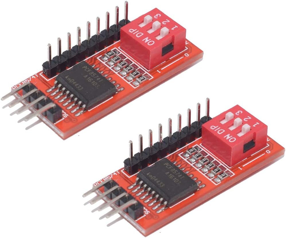
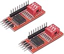

Buy anything from 5,000+ international stores. One checkout price. No surprise fees. Join 2M+ shoppers on Desertcart.
Desertcart purchases this item on your behalf and handles shipping, customs, and support to Thailand.
โก Supercharge your projects with 8x I/O power โ donโt get left behind!
The HiLetgo PCF8574T IO Expansion Board is a compact, dual-interface I2C module that adds 8-bit parallel I/O capabilities to microcontrollers like Arduino and Raspberry Pi. Designed for projects constrained by limited GPIO pins, it supports flexible connection options and is widely used in home automation and relay control applications, delivering reliable performance and seamless integration.
| ASIN | B01ICN5JB6 |
| Best Sellers Rank | #1,550 in Single Board Computers (Computers & Accessories) |
| Brand | HiLetgo |
| Compatible Devices | Arduino, Raspberry Pi, and other single-board computers with I2C interfaces |
| Connectivity Technology | I2C |
| Customer Reviews | 4.0 4.0 out of 5 stars (60) |
| Manufacturer | HiLetgo |
| Mfr Part Number | 3-01-1150 |
| Model Name | 3-01-1150 |
| Model Number | 3-01-1150 |
| Operating System | Linux |
| Processor Brand | Broadcom |
| Processor Count | 1 |
R**F
Work OK
These work good, however they use a 1K pull-up on SDA and SCL. If you have more than one board, This is to low a value. I replaced the resistors with 10K and they work fine.
D**.
Works well with Homeassistant.
Using a single GPIO pin on an esp8266 is not a limitation if a unidirectional port expander can be tolerated. I used this part to operate a 8 relay board. In this case I used an esp8266 d1mini. Here is a working YAML sketch: ------------------------------------------------------------------------------------------------------------- esphome: name: esp8266-8-relay friendly_name: Esp8266_8_relay esp8266: board: d1_mini framework: version: recommended # Enable logging logger: level: debug logs: mqtt.component: DEBUG mqtt.client: ERROR # Enable Home Assistant API #api: #encryption: #key: "q0wRAARhTmThOjrv6MpTmtEduXIIxZ9XNB5RCcWykdY=" ota: password: "a141235ccb9cb645e296e911ecfb09b7" wifi: ssid: !secret wifi_ssid password: !secret wifi_password mqtt: broker: 192.168.11.238 username: !secret mqtt_username password: !secret mqtt_password captive_portal: i2c: sda: D1 scl: D2 scan: true id: bus_a frequency: 50 pcf8574: id: pcf_expander address: 0x20 pcf8575: false switch: - platform: gpio name: "Relay 1" id: relay_01 pin: pcf8574: pcf_expander number: 0 #If the relay starts NC, add inverted: true inverted: true - platform: gpio name: "Relay 2" id: relay_02 pin: pcf8574: pcf_expander number: 1 inverted: true - platform: gpio name: "Relay 3" id: relay_03 pin: pcf8574: pcf_expander number: 2 inverted: true - platform: gpio name: "Relay 4" id: relay_04 pin: pcf8574: pcf_expander number: 3 inverted: true - platform: gpio name: "Relay 5" id: relay_5 pin: pcf8574: pcf_expander number: 4 inverted: true - platform: gpio name: "Relay 6" id: relay_6 pin: pcf8574: pcf_expander number: 5 inverted: true - platform: gpio name: "Relay 7" id: relay_7 pin: pcf8574: pcf_expander number: 6 inverted: true - platform: gpio name: "Relay 8" id: relay_8 pin: pcf8574: pcf_expander number: 7 inverted: true ________________________________________________________________________________ Remember to use the optically isolated function of the relay board for maximum safety.
B**K
Great I/O port
GPIO pins are generally in short supply on most microcontrollers. These boards are a great way to add a couple 8-bit I/O ports to your device. Mine had a base address of 0x20, apparently some have a base address of 0x38. If in doubt code for an I2C scanner can be easily found. You could also just try 0x20 and if that doesn't work then try 0x38. These devices are easily cascadeable, one device can plug into a second (or third, or fourth...) up to a limit of eight. Of course you will have to set the address jumpers provided so each board has a unique address; if your board's base address is 0x20 you can use the jumpers to set it to 0x21, 0x22, ...0x27. One thing I did discover is that you'd be wise to add your own pullup resistors on SDA and SCL; a 4.7k resistor works well. An excellent value for the price.
C**F
If you need to expand the number of I/O pins ...
If you need to expand the number of I/O pins on your Arduino/ESP MCU, look no further than here. This modules gives you 8 digital pins without using any other pins than your I2C bus and power. I am working on connecting mine to a 8-relay module. Since I am working with high voltage, I didn't post any pictures yet. :) Pro Tip: As others have said, the I2C address may be 0x38 or 0x20. If you have an I2C Scanner sketch (and you should), it takes a minute to figure it out. Don't fret. Change is part of life.
S**T
Addressing Issues
This device will not work with any address other than 0x20, even if I only have a single device connected. Whenever the address is changed it causes my Arduino to slowly power down.
N**L
OK. But better ones available.
I bought a couple of these to use while testing another circuit. They did the job and worked fine. But there are a couple of things that could be done to make this better. The board is lacking I2C pullup resistors. There aren't even pads to add your own. I managed to rig a couple onto the bottom of the I2C header pins. Also, the header for the digital IO pins has no ground pin. So there is no convenient place to connect a ground reference while using the digital IO pins. The design works OK, but could have been much better if the designer had included pullup resistor pads and a ground reference pin.
S**V
Worked well!
Got this port expander for interfacing Arduino with 4x4 matrix keypad. It does the job well to save I/O pins on arduino projects.
A**S
Address Pins are grounded on the PCB
The Address pins (A0, A1, and A2) on BOTH the boards I received were grounded on the PCB. The pin outs on the jumpers when holding i/o pins on the top, where VCC, and the next 2 columns were shorted on the PCB between Ground and AO, Ground and A1, and Ground and A2. This prevents you from being able to Unground a pin to pull it high. It also means when you try to pull any Address pin high you short out the VCC to Ground. In order to change the address you must un-solder the Address pins you want pulled high from the PCB.
Trustpilot
1 month ago
1 day ago