ESP8266 220V 10A DC 7-30V Network Relay WIFI Module …
Product ID: 49324514
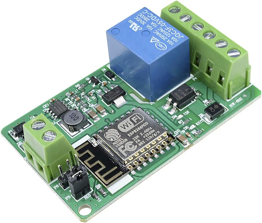
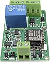
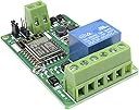
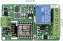
Product Description With ESP8266 Wifi module,4-layers board design. Input overvoltage protection, input with TVS, when voltage exceeds 33V, automatic protection will operate. Input overcurrent protection. 220V 10A relay, one normally open, one normally closed. One way optocoupler isolation input, TVS input protection. High-current terminals. One output status indicator, one input status indicator. More safe with relays PCB pin anti-climb design. Access control server via TCP CLIENT mode Via HTTP protocol control Specifications: Input voltage :DC 7-30V Board dimension:65mm × 40mm × 20mm Package including: 1pcs ESP8266 220V 10A Network Relay WIFI Module
J**T
Good design, but faulty assembly
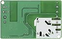
The diode labelled F1 (mine was marked M7 - the SMT version of 1N4007) is soldered in the wrong way and needs turning 180 degrees. In the correct position, the markings (anode) should point towards the capacitor C4 (see pictures). This seems to be an issue with several of these modules!!The ESP8266 doesn't seem to have any useful software installed. It spins up a soft AP and DHCP server, but I couldn't find any services running. To re-flash some other software, you will need to: - solder the 3 pin header (TX, RX, GND) and connect a Serial FTDI Adapter or cable - Note that the TTL levels of the ESP8266 are 3.3V and NOT 5V tolerant! - solder the 2 pin header (BOOT, GND) and connect them before flashingHelpful hints when writing your own code:- GPIO4 is used to control the relay, the connector is (NC, COM, NO) top-to-bottom- the other connector is (+5V, INPUT, GND), with the input being made available to GPIO5 via optocoupler- INPUT and RELAY have their own LEDs when active, the blue LED on the Wifi module is attached to GPIO2.- The other GPIOs and ADC are not broken out, but can be easily soldered onto the ESP-12 module. Again, 3.3V levels.Happy Hacking!
J**S
No password info supplied
The package doesn't contain any information on the WiFi password. After a lot of Googling and guessing, it still wouldn't respond. Unless you are willing to somehow re-program it, it is a waste of money!
Trustpilot
1 day ago
1 month ago