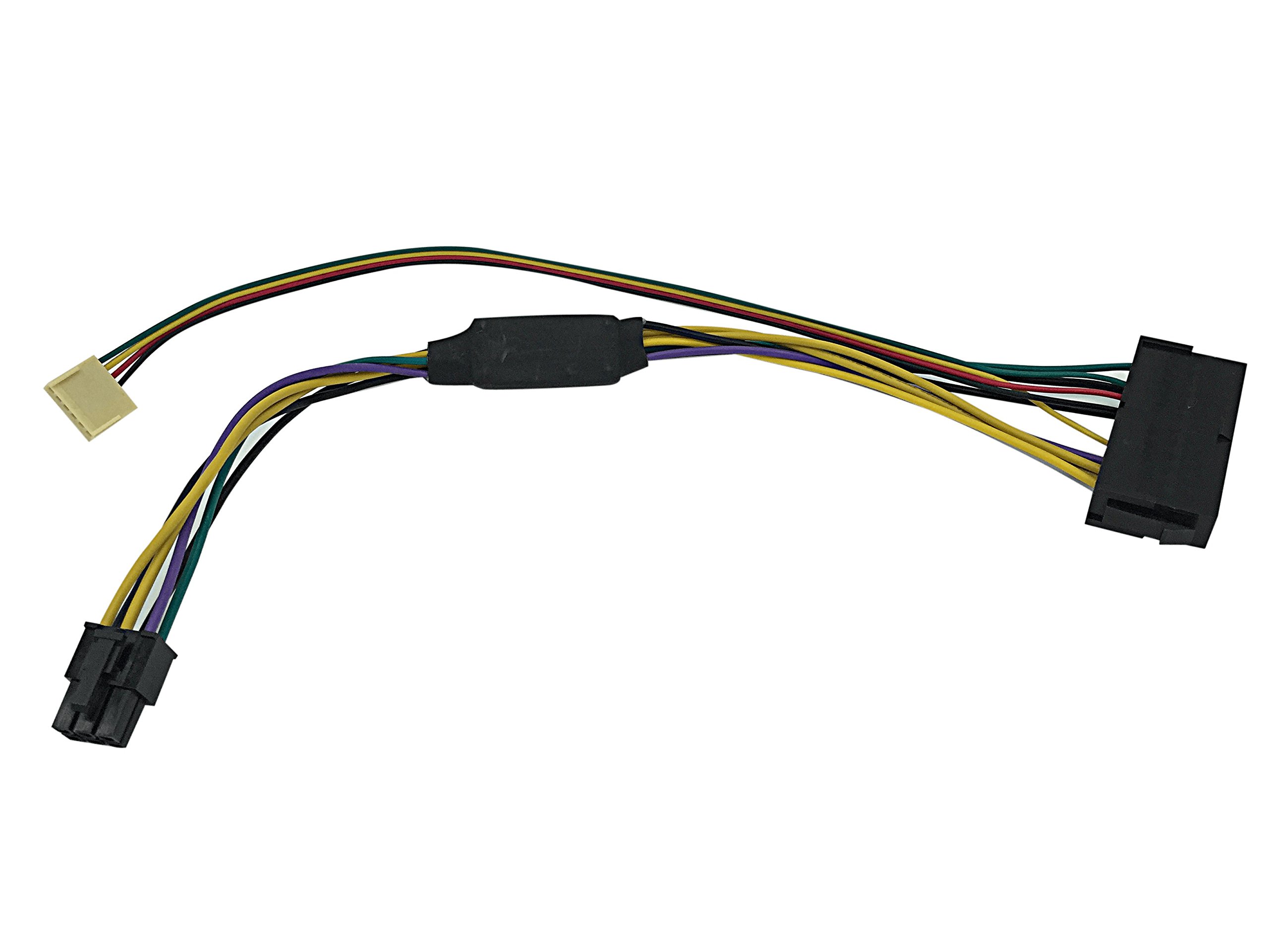
Buy HP Z230 motherboard 6-Pin 6P to 24 Pin ATX Power Supply PSU adapter cable: Internal Power Supplies - desertcart.com ✓ FREE DELIVERY possible on eligible purchases Review: Good luck to all converting business proprietary PCs to budget ... - I bought this adapter for my HP Compaq Elite 8300 CMT so it would work with a standard ATX power supply. The adapter works and steps up to the right voltages, however, the straight 6-pin connector is wired incorrectly. I had to pull out the leads and have a wiring diagram and voltmeter to guide me. Eventually this worked with green at the bottom, yellow, red and black at the top. I docked only two stars because I expected this product to work, but was made incorrectly and due to the amount of effort it took to get it to work for me. I kept the three stars because there isn't an alternative cable offered anywhere else. Good luck to all converting business proprietary PCs to budget gaming rigs :) Review: Connect slot 2 on the P2 connector to the chassis fan tac signal to stop the 515 FAN boot error - HP 8200 Elite CMT For Pin # reference the green wire 'PS On" wire on original 6 pin P2 connector is Pin 3. Move the green wire to Pin 3 on the new P2 connector. The empty reserved slots on the original P2 connector are pins 5 + 6. No wire needs to be connected to pins 5 + 6. Leave Pin 1 "FAN CMD" empty as the Black and Red wires on the new P2 connector go to ground pins 17 + 18 on the 24 pin ATX connector. The Yellow wire Power Good wire goes to PIN 4. Cut the Red wire close to the 24 pin AXT connector. Connect cut end of the red wire to the TAC signal gray wire of the Chassis Fan. The other end of the red wire goes in slot 2 of the new P2 connector. Pin 1 slot leave empty Pin2 slot red (connect the other end to chassis fan tac wire, my wire was gray) Pin3 slot green Power on (pin 16 on 24 pin ATX connector) Pin4 slot Yellow (Power Good pin 8 on 24 pin ATX connector) Pin 5 slot leave empty Pin6 slot leave empty The Black wire is grounded at the 24 pin ATX connector so it wire does not need to be connected to the new P2 connector. Connecting slot 2 on the P2 connector to the chassis fan tac signal stops the 515 FAN boot error!
| ASIN | B01MT5DSXG |
| Brand | Eyeboot |
| Cable Type | HDMI |
| Compatible Devices | Personal Computer, Server |
| Connector Gender | Male-to-Female |
| Connector Type | 6 Pin Atx, 24 Pin Atx |
| Customer Package Type | Standard Packaging |
| Customer Reviews | 3.7 3.7 out of 5 stars (3) |
| Date First Available | June 12, 2017 |
| Indoor/Outdoor Usage | Indoor |
| Is Discontinued By Manufacturer | No |
| Item Weight | 1.76 ounces |
| Item model number | 820055-B2C-6P24P |
| Manufacturer | Eyeboot |
| Maximum Voltage | 12 Volts |
| Number of Pins | 30 |
| Product Dimensions | 11.81 x 0.39 x 2.36 inches |
| Recommended Uses For Product | Connecting desktop computers (HP Z230 motherboards) |
| Shape | Round |
| Wattage | 1000 watts |
V**V
Good luck to all converting business proprietary PCs to budget ...
I bought this adapter for my HP Compaq Elite 8300 CMT so it would work with a standard ATX power supply. The adapter works and steps up to the right voltages, however, the straight 6-pin connector is wired incorrectly. I had to pull out the leads and have a wiring diagram and voltmeter to guide me. Eventually this worked with green at the bottom, yellow, red and black at the top. I docked only two stars because I expected this product to work, but was made incorrectly and due to the amount of effort it took to get it to work for me. I kept the three stars because there isn't an alternative cable offered anywhere else. Good luck to all converting business proprietary PCs to budget gaming rigs :)
R**N
Connect slot 2 on the P2 connector to the chassis fan tac signal to stop the 515 FAN boot error
HP 8200 Elite CMT For Pin # reference the green wire 'PS On" wire on original 6 pin P2 connector is Pin 3. Move the green wire to Pin 3 on the new P2 connector. The empty reserved slots on the original P2 connector are pins 5 + 6. No wire needs to be connected to pins 5 + 6. Leave Pin 1 "FAN CMD" empty as the Black and Red wires on the new P2 connector go to ground pins 17 + 18 on the 24 pin ATX connector. The Yellow wire Power Good wire goes to PIN 4. Cut the Red wire close to the 24 pin AXT connector. Connect cut end of the red wire to the TAC signal gray wire of the Chassis Fan. The other end of the red wire goes in slot 2 of the new P2 connector. Pin 1 slot leave empty Pin2 slot red (connect the other end to chassis fan tac wire, my wire was gray) Pin3 slot green Power on (pin 16 on 24 pin ATX connector) Pin4 slot Yellow (Power Good pin 8 on 24 pin ATX connector) Pin 5 slot leave empty Pin6 slot leave empty The Black wire is grounded at the 24 pin ATX connector so it wire does not need to be connected to the new P2 connector. Connecting slot 2 on the P2 connector to the chassis fan tac signal stops the 515 FAN boot error!
A**D
Three Stars
needed some rewiring to work
Trustpilot
3 weeks ago
1 month ago